Differential Flexure
These two images show part of the Crescent Nebula. The left image was taken with a basic 9¼" Schmidt-Cassegrain telescope, while the image on the right was taken with a premimum 5" refractor. Both telescopes were precisely focused before exposing these images. Why isn't the premium image as sharp or sharper than the SCT image?
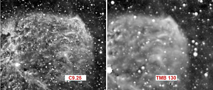
The answer is differential flexure – bad news for anyone trying to guide a telescope with a separate guide scope and camera instead of with a second sensor inside the main camera, or an off-axis guider attached to the main camera.
What's Going On?
Differential flexure occurs when part of the imaging system shifts slightly relative to other parts. These parts may be the guide scope and focuser, the guide camera, the main telescope and focuser, and/or the main imaging camera.
As the telescope tracks across the sky, gravity can cause some components to sag slightly, so the guide scope and the main scope no longer point precisely at the same spot in the sky. The autoguider keeps the guide star centered, but the image on the main camera moves relative to it, resulting in smeared stars and fuzzy details.
See for Yourself
This is a stack of 17 5-minute subframes, combined without "registering" the individual subs to align the stars.
Explanation: Registration shifts individual subframes so the stars line up. Skipping this step means the stars in each subframe appear in the combined image at their original positions, so any movement that occurred from one sub to the next shows up as trailed stars.
The movement is very small. Visually, the stars in each sub might appear round, but they are not round. The trailing might be too small to see in a subframe, but the combined image reveals the movement.
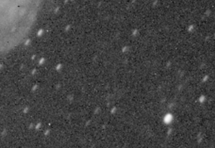
When image-processing software shifts the subs to align (register) the stars, non-stellar objects are blurred, such as the nebula at the top of this page.
Tiny Movement
Close inspection of this composite image in Photoshop revealed the total displacement is roughly 11 pixels horizontally and vertically, or about 16 pixels diagonally. The image scale is 2 arc-seconds per pixel, so something moved 32 arc-seconds during the 85 minutes the 17 subs were being exposed, or about 2 arc-seconds during each 5-minute exposure.
Just how much mechanical movement does 2 arc-seconds (1/1800 of a degree) represent? Very little! Assuming the guide scope focal length is 12" long (304mm), simple trigonometry reveals that 2 arc-seconds represents a movement of 0.000116 inches – that's 116 micro-inches, or about 1/32 the thickness of a human hair. Precision machinist instruments can't measure this, and you certainly can't feel it by wiggling the equipment with your hand. You don't know the movement is there until it ruins an image.
Hard to Track Down
What does this all mean? It means you should try everything you can think of to eliminate differential flexure. It's a lot of work, but keep trying.
Even after making several modifications to my guide scope, and temporarily replacing my Pyxis camera rotator with a solid tube of the same length to eliminate it as a suspect, a series of 5-minute exposures still showed movement of about 2 pixels during a single subframe exposure. This is the same 2 arc-seconds described above – no improvement at all.
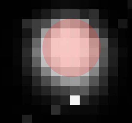
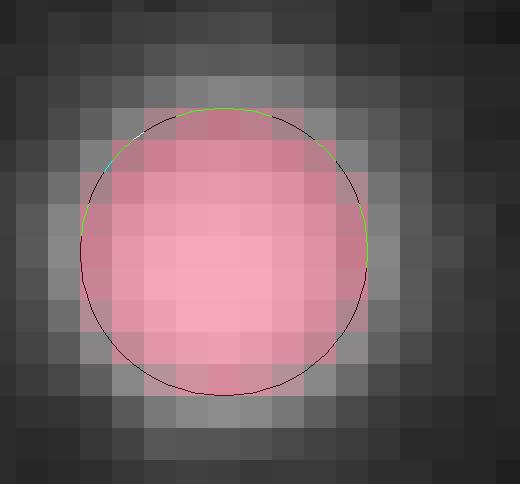
Here is a single subframe showing an elongated star with an ideal circle (pink) superimposed over the brightest pixels. The dim pixels beyond the pink circle on the sides and bottom are obvious.
Good News (2007)
I'm pleased to report that my flexure problems are fixed! This hydrogen-alpha image of NGC6992 is a stack of 30-minute (not 5-minute, as above) subframes that were made after performing the modifications described in the table below.
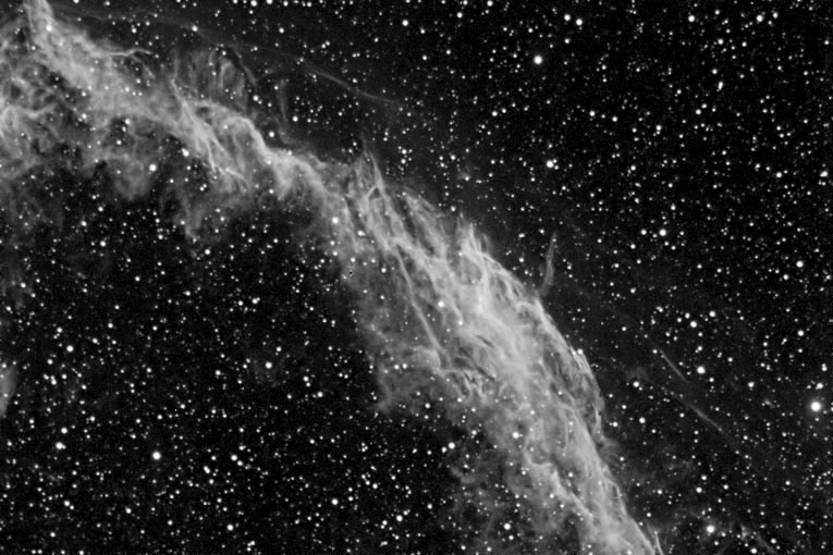
This is a single star enlarged from one NGC6992 subframe. Compare this 30-minute exposure with the 5-minute elongated-star image above. No elongation is evident over this long exposure.
What Eliminated My Differential Flexure?
In 2007 I made these modifications to my equipment in the quest to eliminate differential flexure. I can't say for sure which one (or several) did the trick, but I'm confident each was worth the effort, and all remain in place to this day.
|
Modification
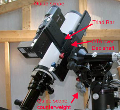
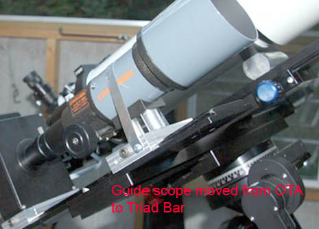
Installed a Robin Casady Triad Bar.
Note: The Triad bar was overkill because I didn't need to mount three telescopes. A Tandem Bar would have sufficed.
Update, January 2020: Robin Casady is selling off existing stock, but not replacing it.
|
Why?
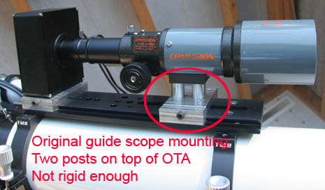
Perching the guide scope on top of the main OTA rings means that any movement of the rings is amplified. The Triad Bar places the guide scope low on a very solid bar, so movement is eliminated.
|
|
Modification
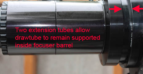
Added a second 2½” threaded extension tube between the focuser and the camera.
|
Why?
Originally I had a single 2½” extension tube, but this required the focuser drawtube to be racked-out nearly three inches. The extra extension tube allows 2½” more of the drawtube to be supported inside the focuser housing, reducing droop.
|
|
Modification
Replaced my original Delrin spacer blocks under the main telescope mounting rings with new ones made of aluminum.
|
Why?
Two people suggested the Delrin might be expanding or contracting at a different rate than the aluminum in the rest of the system. Or, being a slippery plastic, the blocks might be sliding. I wasn't convinced these were factors, but I replaced the Delrin with aluminum anyway.
|
|
Modification
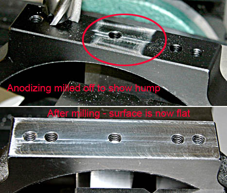
Milled-flat the bottoms of the main telescope mounting rings.
|
Why?
After machining the new aluminum spacer blocks, I set the base of a mounting ring on one and was astonished to see it rock back-and-forth. There was a 0.010" hump in the center of the ring base! The second ring had a similar hump. I milled both ring bases flat, and now they rest firmly on the spacer blocks.
|
|
Modification
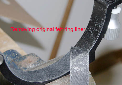
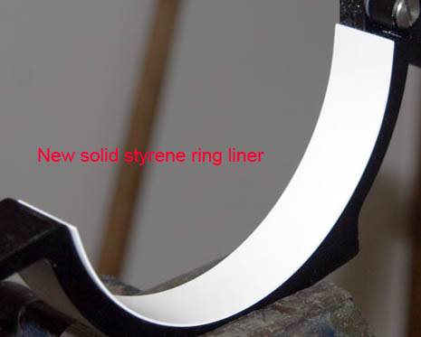
Replaced the felt lining in the main telescope mounting rings with solid styrene strips.
|
Why?
A friend suggested that the felt lining in the mounting rings might compress as the telescope weight shifts while tracking across the sky. Given the extremely tiny movement needed to produce elongated stars, this seemed very likely. I measured the thickness of the rubber-backed felt and found it would compress more than 0.005" with only light finger pressure.
I removed the felt, cleaned the adhesive residue from the rings, cut strips from 0.030"-thick sheet styrene (available at hobby shops), and affixed them to the inside of the rings with CA adhesive (cyanoacrylate, or "super glue"). I clamped the rings around the telescope to press the styrene tightly until the CA cured.
I was fortunate that the 0.030" styrene was just right. Otherwise, I would have combined several layers of styrene to reach the needed thickness.
|
|
Modification
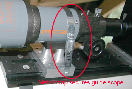
Added a metal strap to the guide scope mounting.
|
Why?
Originally, the guide scope was mounted on two short aluminum posts. A friend commented he once used a similar arrangement but needed a metal strap, so I added a hose clamp over the scope, with the cut ends screwed to the dovetail mounting bracket. In addition, as described above, I moved the guide scope from atop the OTA to the Triad Bar.
|
|
Modification
Added a "back rest" to the guide camera.
|
Why?
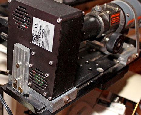
Notice in the top photo above that the guide camera is clamped to the dovetail plate, not supported by the guide scope focuser. Hanging a camera off a small focuser like this can cause major flexure.
The guide camera is attached to a dovetail clamp with a ¼"-20 bolt into a tripod socket on the camera bottom. But the camera's thin metal case allows it to tilt backward when pointing high in the sky – flexure in its most basic form!
To prevent this, I machined a ½"-thick aluminum support, and screwed it to the back of the camera and to the dovetail bracket. Now the guide camera is held securely at all angles.
Click here to learn how I focus the guide camera.
|
Updated
December 22, 2024